How Sensor Taps Works
HOW AUTOMATIC SENSOR TAP WORKS
Our automatic sensor taps combine four key components: Solenoid valve, infrared sensor, power source, and a tap unit/shell.
Solenoid valve
Transforming electrical energy into motion, the solenoid physically starts and stops the water flow.
Autotaps products use "latching" solenoid valves. The solenoid valve is initially energized to start
the water flow; the plunger is driven into the range of a permanent magnet which in turn holds
the plunger in the "open" position. In order to return the plunger into its original "closed" position
the solenoid is once again "pulsed" but this time by reversing polarity.
Infrared sensor component
When the sensor senses the presence of an object (i.e. user’s hands) in front of the tap and sends a signal
to the solenoid valve to initiate the flow of water. When the object is no longer present, the infrared unit
sends an electronic signal to the solenoid valve again to terminate the flow of water usually after a few seconds.
Power source
Most of our Autotaps models have the possibility to be powered by regular AA batteries (Alkaline) or
by mains via a 6V transformer. Batteries and transformers are included with most of our products.
Solid Brass body
The body/shell delivers the water. Autotaps puts special emphasis in design and quality. Even if the tap
is electronic it must be in tune with the style of every specific place. Autotaps produces electronic taps with
different styles to match every decorative theme.
DIAGRAM
Quick Explanation
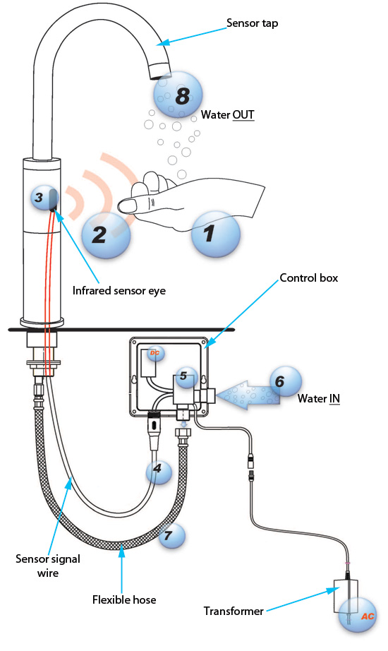
An object '1' disrupts or enters the proximity sensor zone '2', the infra red sensor '3' detects the object and sends an electronic signal to the solenoid valve '5' (inside the control box) via a signal wire '4'. The solenoid valve opens up to let water supply '6' through it, and water is fed to the user '8' via the flexible hose '7' connected to the tap.
DETAILED EXPLANATION
1- Object/Hands
An object i.e. hands approaches the sensor eye '3'
The infrared proximity is triggered or disrupted once an object enters its infrared sensing zone '2'
2- Infrared sensor range
The proximity sensor zone is live once powered (Typical sensor range 20-26cm wide)
3- Sensor eye
The sensor eye part beams out infra red signal
4- Sensor signal wire
The sensor signal wire transfers or sends an electronic signal to the solenoid valve '5' to OPEN or CLOSE
5- Solenoid valve
The solenoid valve acts as a latching mechanism that restricts or allows water to flow through it.
It opens up and releases water through the flexible hose '7' as soon as an electronic signal is received from the sensor '3'. The solenoid valve is always in CLOSED position, and opens up once an electronic signal is received, it goes back to CLOSED position when the object '1' leaves the infra red sensing zone '2'
6- Water IN (Hot, Cold or Premix water): Entry
Main water supply entry.
7- Water OUT passage (Flexible hose)
The flexible hose transfers water released from the solenoid valve '5' to the sensor tap '8'.
8- WATER OUT: Exit
Water exits- Water let through the solenoid valve comes out
DC- Direct Current- Battery compartment
AC- Alternate Current: Transformer connected to mains power supply